- Home /
- Fire Pumps /
- SAM™ Control System
Features
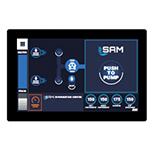
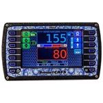
The SAM control center provides the user with an overview of the status of intakes, discharges and tank at a glance and allows for quick, efficient control of the water flow.
The system does the following:
- Automatically opens the tank to pump valve when it sees it is in pump gear.
- When the operator then selects a discharge, sets a pressure for that discharge then SAM charges the line and adjusts engine speed as needed and maintains the desired set pressure for each discharge.
- Automatically transitions to an external water source. When an external water source is ready the operator selects the intake, tells the system to open it and SAM takes action.After transitioning to external source, the system refills the tank
- If transitioning to a pressurized source the system will bleed air from the line, open the intake valve and manage the engine speed during transition to keep discharge pressure steady.
- If drafting, the system will pre-prime up to the intake valve then open the intake once the prime has been established.
Applications/Solutions
- Emergency Responder OEMs
- Fire OEMs
- Firefighting - Airport (ARFF)
- Firefighting - Industrial
- Firefighting - Structural
- Specialty Vehicles
SAM™ Control System Video


Specifications
| Style | SAM |
|---|---|
| Country of Manufacture | US |
| Weight | To Be determined based off final configuration |
| Brand | SAM |
| Length | To Be determined based off final configuration (To Be determined based off final configuration) |
| Width | To Be determined based off final configuration (To Be determined based off final configuration) |
| Height | To Be determined based off final configuration (To Be determined based off final configuration) |
SAM Control System Detailed Specifications
SYSTEM FUNCTIONALITY
A SAM control system shall be provided. The control system shall automatically control the following elements of the pumping process:
- Open tank-to-pump automatically and re-circulate water as needed to protect the pump
- Open discharge valves and charge to an operator set pressure and then maintain that pressure by gating the discharge valves as necessary and/or managing the pump discharge pressure.
- Control engine speed as needed to maintain individual line discharge pressures set by the operator
- Automatically switch sources from tank to hydrant or from tank to draft functions at the operator request without requiring the operator to independently manipulate the valve positions
- Automatically refill the tank when secondary water supply is available
- When flowing from a pressurized source, the system will monitor the intake pressure and reduce engine speed so it does not drop below purchaser specified pressure 10-30psi and alert the user if the system has low supply pressure
- Alert the operator audibly and visually of any problems with the system or with water flow and pressure settings
The system shall include automatic control of the following system components:
- Intake valve(s)
- Tank-to-pump valve
- Tank fill valve
- Discharge valve(s)
- Engine speed
The system shall accomplish the above by having the discharge valves, intake valves, and pressure governor on networks with all components in communication with each other at all times. These components must be configured, networked, and tested as part of the pump assembly prior to shipment to the OEM.
The system shall operate in two modes – automatic and manual.
The system shall include a control center interface, a pump controller interface and a throttle control knob which provide all necessary system control in both automatic and manual mode.
SYSTEM CONTROL INTERFACE SCREENS
Control Center
Automatic mode: The interface shall include the following features available
- It shall display up to six (6) active discharges in discharge control boxes Within each box, it shall show the set pressure and the actual pressure of the discharge. It shall indicate the color of the discharges in each discharge box as well as display any the status of the active discharges and provide a low flow indication if the nozzle is closed or there is a kink in the line. It shall also indicate if there are any problems with the valve and shall indicate whether CAFS or FOAM is active if a SmartFOAM or SmartCAFS system is included.
- It shall show the available intakes and the status of the intake valves.
- It shall show the water tank level and foam tank level
- It shall show the status of the tank and indicate whether the intake(s) is supplying water to the pump or whether the tank is supplying water to the pump
- If an intake valve is open, the control center shall display the intake pressure
- It shall include four configurable quickset circles that can be used to quickly set the pressure and open discharge lines by dragging the quickset circles to the target in the discharge area of the display
- It shall include an information center to indicate things that are happening with the system as they are occurring
- It shall include pop-up warning boxes to indicate any problems with the system or warning regarding water flow throughout the system
When in auto mode, the control center interface shall allow the operator to do the following from the interface:
- Set pressure on individual discharges
- Adjust the set pressure
- Close the discharge line
- Select an intake to open
- Select whether the intakes are set to draft or pressurized water source
- Switch back to tank water and close the intake
When in automatic mode the operator will not be required to operate any individual discharge valves, governor settings, or any individual intake settings.
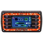
IF SmartFOAM or SmartCAFS system is installed, the operator shall be able to also do the following from the control center:
- Turn on CAFS to wet, medium or dry or foam only from the discharge control screen
- Turn on FOAM to a preset percentage from the discharge control screen
- Turn CAFS or FOAM off
Manual mode: The control center interface shall include a manual mode. When in manual mode, the operator shall have control over each of the intakes and discharges from the control center. Each discharge valve shall show line pressure and valve position and allow the operator to open and close the valve. The manual control screen shall include a way to send the system back to auto mode if the operator chooses.
The control center shall be a 10.6” display with a bonded LCD, anti-glare coating and PCAP touch screen. It shall include two (2) CAN network inputs and a USB 2.0 connection. The operating voltage shall be 6-36VDC, shall have an operating temperature of -40°F to 185°F and shall have a environmental rating of IP67.
Pump Controller
Automatic mode: When the system is in auto mode, the interface shall include the following features:
- A separate touch screen interface consisting of several pages that can be accessed by the operator. These pages to include:
- Home screen
- Tank
- Pump info
- Video
- Engine Data
- The home screen shall include master intake pressure, master discharge pressure and engine speed, status of tank fill and tank-to-pump valves, pump capacity and status box that indicates system is in AUTO mode. The pump capacity shall be a real time indication of the current flow and available flow from the pump based on intake pressure and other dynamic factors used to calculate the real time pump capacity at high flows. The flow shall update automatically as conditions change.
- The tank screen shall indicate status of tank-to-pump and tank fill valves as well as an indication that tank-to-pump and tank fill valves are being automatically controlled by system in auto mode.
- The pump information screen shall include the following information:
- Pump capacity
- Anode status for three (3) installed anodes
- Gearbox oil status
- Autolube oil status
- Gearbox temperature
- Pump temperature
- Pump details including: Pump Model, Rating, Gearbox, Gear Ratio, Pump Assy Plate No, Gearbox Assy Plate No, Manufacture date, Hale Pump Factory Test Data
- The video screen shall include a display of a video feed and allow the user to toggle between up to three (3) available video inputs.
- The Engine Data screen shall include battery voltage, coolant temperature, oil pressure, transmission temperature and warnings.
Manual mode: The pump controller interface will revert to standard pressure governor operations when manual mode is requested by user or when the system defaults to manual mode.
The pump info, video and engine data tabs shall be the same as operation described in auto mode. The home screen and tank screen shall have the following functions.
The home screen shall include pressure governor controls, pump capacity indication and tank-to-pump and tank fill valve status indication. The home screen shall include the following:
- Mode select. Allows the user to select PSI or RPM mode
- Master intake and master discharge pressure display
- Increase and decrease buttons to increase and decrease the pressure or RPM depending on what mode is selected
- User configurable quickset circles for pressure and RPM
- Indication of set pressure when in PSI mode
- Status of tank fill and tank-to-pump valve and indication if system is recirculating
- Pump capacity indication
The tank screen shall include control of the tank-to-pump and tank fill valves and indication of valve position. The operator shall be able to open or close the tank fill and tank-to-pump valve when in manual mode.
The pump controller shall be a 7” display with a bonded LCD, anti-glare coating and PCAP touch screen. It shall include three NTSC/PAL video inputs, two (2) CAN network inputs and a USB 2.0 connection. The operating voltage shall be 6-36VDC, shall have an operating temperature of -40°F to 185°F and shall have an environmental rating of IP67.
Throttle Control Knob
A throttle control knob shall be provided to control the speed of the engine. The throttle control knob shall include a master IDLE button that sends the engine to IDLE and switches the SAM system to manual mode when pressed. The throttle control knob shall communicate using J1939 CAN data link protocol. It shall have two indicator LEDs on it. One to indicate ACTIVE and the second to indicate THROTTLE READY. The operating voltage shall be 9-32VDC, shall have an operating temperature of -40°F to 185°F and shall have a environmental rating of IP67.
SYSTEM WARNINGS
The system shall provide audible warnings when the following conditions occur:
- Pump Engaged, SAM ready
- SAM disabled
- Discharge Opening
- Low Intake Pressure
- Low tank water
- Out of water
- Hydrant established
- Draft established
- Draft problem
- High LDH Pressure
SYSTEM REQUIREMENTS
The system shall allow for the following number of valves:
- Four (4) intake valves
- Twelve (12) discharge valves
- One (1) tank-to-pump valve
- One (1) tank fill valve
The system requires that the following components be specified:
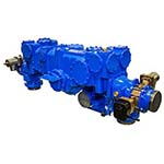
- Qmax or Qmax-XS pump
- Akron Brass electric valves for all discharge valves
- HALE electric MIV intake valves
- Class 1 ITL-40 tank level gauge
- Hale SPV Primer
The system shall include all necessary harnessing and electronic modules to provide system functionality described above. The system shall be shipped from the pump manufacturer with all required valves, electronic modules, sensors, harnessing and panel mounted components necessary for the function of the system. The system shall be configured and tested at the pump manufacturer prior to shipment to the OEM.
SYSTEM OPTIONS
Optional SAM accessories shall be available with the system. The optional accessories include:
- Secondary Control Center display that includes the same control as the primary control center. A third vehicle mounted screen can also be added.
- Wireless Control interface that mimics the control center display
Documents
| Name | Sheet # | |
|---|---|---|
 |
|
Installation and Service Documents
Contact Us with Questions
| Name | Sheet # | |
|---|---|---|
 |
||
 |
||
 |
Software Updates and Downloads
Contact Us with Questions
| Type | Description | Instructions | Version | Updated | File |
|---|---|---|---|---|---|
| 2021-08-04 19:17:01 |
Product Updates and Media Files
| Description | Type | Size | |
|---|---|---|---|
| SAM Control System - End User FAQs | n/a | ||
| SAM Control System - Overview for End Users | n/a |
Related Products

|
SmartFOAM... |
|
SmartFOAM is a direct injection foam proportioning system that has been engineered to work smarter for you. S... |

|
Qmax Single Stage Water Pump... |
|
Hale’s Qmax single-stage centrifugal fire pump generates NFPA 1901 rated flows of up to 2250 GPM (8515 LPM). The one-p...
|

|
Qmax-XS... |
|
Hale’s Qmax-XS pump’s high water delivery rate to knock down large fires, proven reliability based on the impressive...
|

|
ITL-40... |
|
The ITL-40 Tank Level Gauge features a true 180 degree viewing angle with super bright LED's and built-in diagnostic "te...
|

|
SmartCAFS... |
|
SmartCAFS is a Compressed Air Foam System that works smarter for you. Using a Compressed Air Foam System has traditio... |

